for future expansion
for future expansion
|
|
click on nr. to see the corresponding screen for each switch position |
|
|
|
|
|
|
|
|
|
|
|
|
|
|
|
|
show me a specification listing of all switch positions
view all modes
the above window is what you actually will see on your PC screen (the scoll bar doesn't work in this demo but will on your PC)
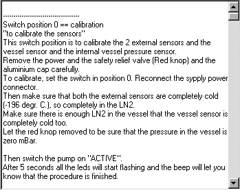
view all modes starts with switch position 0 and describes all other positions
below you can click for all 16 switch positions and scroll through the entire list
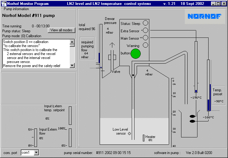
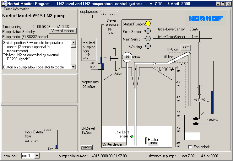
time running
the time indicated is the elapsed time since the system is connected to power
the pump status (standby or sleep) has no influence on this reading
pump model nr
the model number is read from the actual pump connected, in this sample a #915-model pump
the monitor software adapts itself to the pump in question
so when in real life e.g. a #905-series pump (which has less possibilities) is connected to the PC some features as shown in this demo with a #915-pump are not applicable
the pumpstatus can be "sleep" or "standby"; the status is changed by pressing the green knob on the front
pump status
the pumpstatus can be "sleep" or "standby"; this status ic changed by pressing the green knob on the front
when in "sleep", only the risepipe freeze protection is ON, there is no further action and the status LED on the pump flashes at a very low speed
when in "standby", the pump acts according to the position of a built-in multiposition switch
to see what happens if this pump is set to "standby" move your cursor over "status" in "Pump status" observe that the status reading changes as well
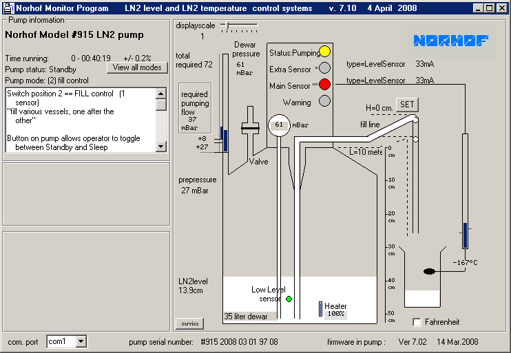
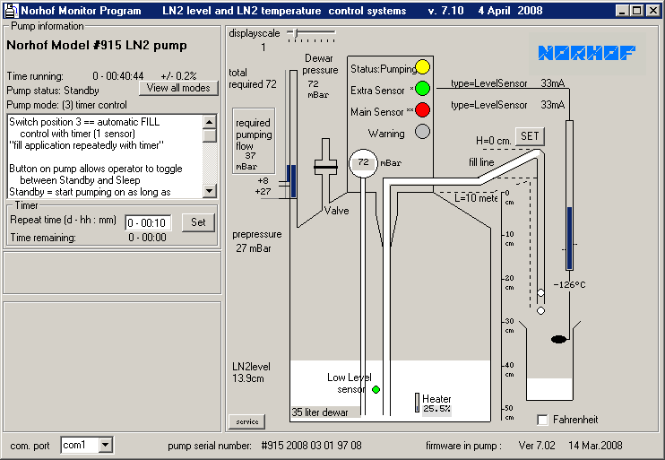
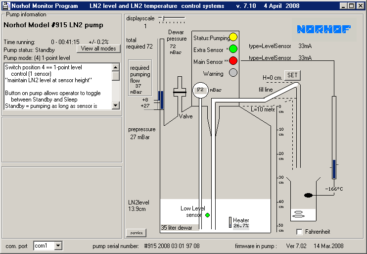
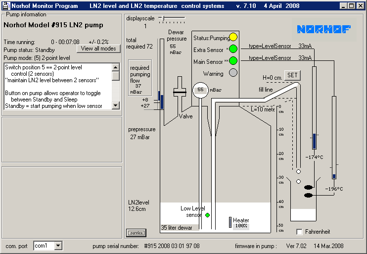
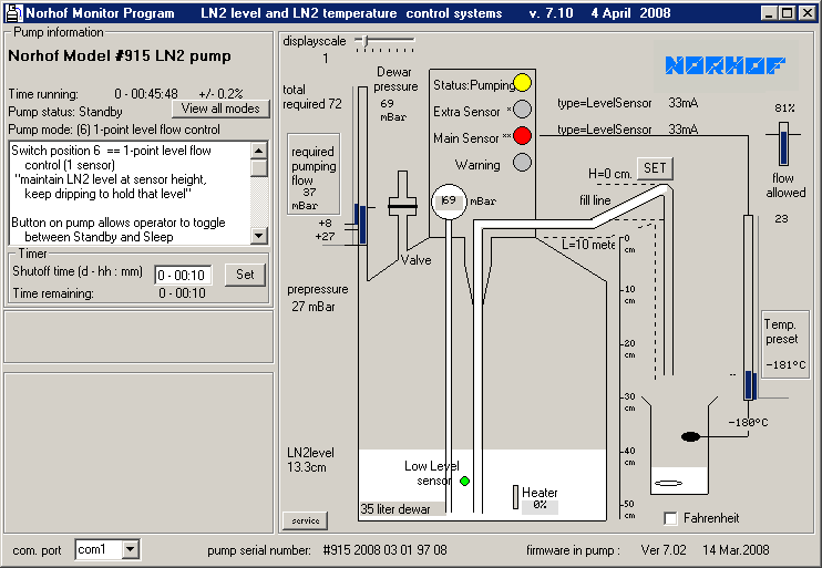
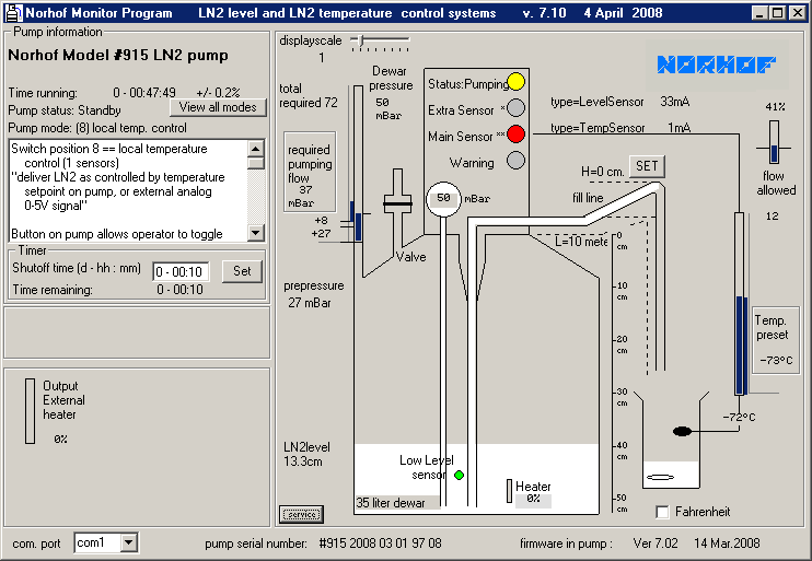
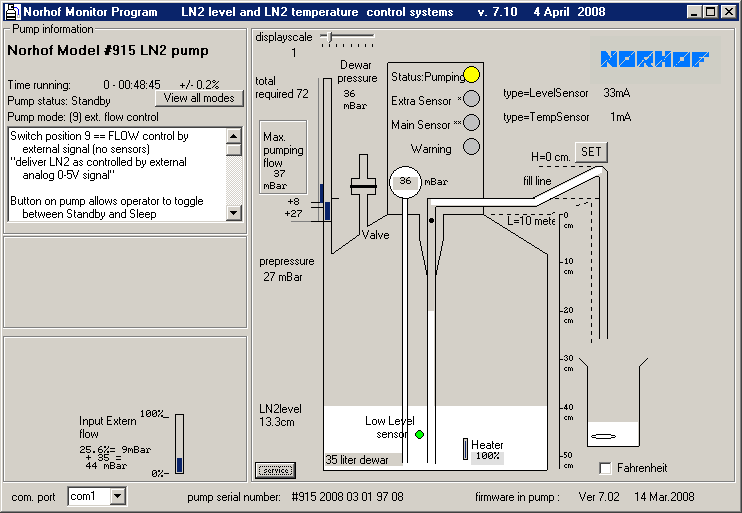
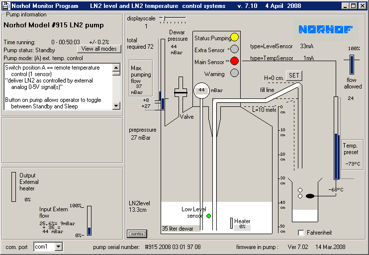
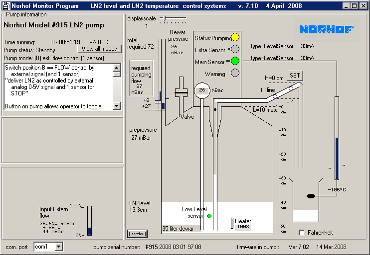
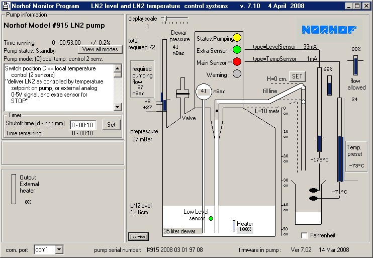
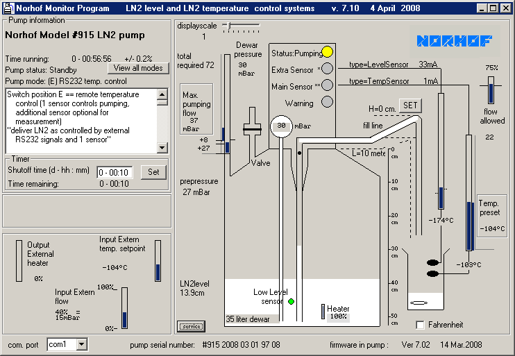
pump mode
the position of a 16-position switch inside the pump housing dictates the behaviour of the system
in this demo the switch is in position 5 (2-point level control)
observe that the details of the position selected are listed in the white section (the scoll bar doesn't work in this demo but does on your PC)
after having used the system for some time, you may have forgotten what the other positions do; therefor all switch positions are described in detail under "view all modes" please realise that this data is resident in the pump itself, so you don't need a manual if the application changes and you need to adapt the behaviour of the system accordingly
all you have to do is to put the switch in another position (e.g. to change from 2-point level control to temperature control means switching from position 5 to position 8)
below you can click for all switch positions, in that overview the exact specifications of each switch position is given
pre-pressure
pre-pressure is the pressure needed to bring the liquid level inside the risepipe just under the pumphead
this value is fixed and depends on the inner height of the used dewar
+8 mBar
this value is standard factory setting for the extra pressure required for the liquid to reach the pumphead
presssure bargraphs
the left bargraph displays the required pressure
note the small blue bar
this bar grows or shrinks according to the setting of the flow potentiometer on the pumpbody, but remains steady when set
in this demo the value is 64mBar
the right bargraph dynamically displays the actual pressure inside the Dewar
in this demo the value is 55 mBar at this moment
therefor you'll always have pre-set and actual pressure next to each other in view
it is easy to see that full flow is not yet established, because the right graph is not yet at the same level as the left graph
total required pressure
is the sum of
+pre-pressure = the pressure needed to raise the liquid level inside the storage Dewar to the pumphead (here 27 mBar)
+feeding height = the pressure needed to get the liquid to the highest point in the fill line (here 8 mBar)
the value is set on a PC screen with "SET" button
after setting the value the PC is no longer needed
+required
flow = value
is set on the pump by numbered thumbwheel (here 37 mBar) ![]()
or by remote signal (e.g. 0-5V= or RS232)
valve display
the status of the vent valve built into the pump head is dynamically displayed
now the valve is closed; at the end of a fill cycle the valve is opened and is displayed accordingly
required pumping flow
is the setting
of the flow potmeter on the pumpbody ![]()
or from external signals
dewar pressure
the reading is the actual overpressure in the bottom of the Dewar relative to the atmospheric pressure
in this demo the value is 55mBar
status LED (yellow)
- blinks slowly in standby mode
- blinks fast in active mode
- is ON when pump is in action
extra sensor LED (bi-color)
- green: sensor is warm / dry
- red: sensor is cold / wet
- blink: sensor is broken / shorted
main sensor LED (bi-color)
- red: sensor is warm / dry
- green: sensor is cold / wet
- blink: sensor is broken / shorted
warning LED (red)
- blink: general alarm
- ON: refill vessel + every 30 sec a double beep as reminder to refill the vessel
level sensor
a level sensor inside the Dewar senses when the liquid level drops below it
if so a signal is generated and on the PC screen the green spot becomes red
this is a timely warning
usually you may continue working for at least another day before the system shuts itself off because the Dewar is empty
heater
a heater is used to generate the required overpressure
the heat capacity applied depends a.o. upon the required flow
by observing the percentage you'll quickly develop a feel of how the system performs
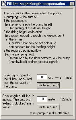
feeding height
this window pops up when you press the "SET" button on your PC screen
in order to compensate for major height differences in the fill line all you have to do is to type in the height difference between the pump exhaust and the highest point in the fill line
when pressing the "write in pump" button the value you have typed is written into the pump memory and you have compensated for the extra height
this setting is of interest when the fill line runs e.g. over a 2-mtr high barrier
this compensation is resident in the pump; you only need a PC to change the value
temperaure bargraphs
these bargraphs indicate the temperature of the sensors connected to the system
note the small horizontal black lines on either side of the graph
these are the setpoint indicators
these setpoint indicators are dynamic and the vertical position along the bargraph change with the application setting
note also that you actually can see that higher sensor is warmer than the lower sensor and that you can read what their respective temperature is
in addition you can also see that the higher sensor is above setpoint and the lower has not reached it's setpoint yet
total required pressure=
+pre-pressure
the pressure needed to raise the liquid level inside the storage Dewar to the pumphead
+feeding height
the pressure needed to get the liquid to the highest point in the fill line
the value is set on a PC screen with "set" button
after setting a PC is no longer needed
+required flow
value is set on the pump by numbered thumbwheel or by remote signal (e.g. 0-5V= or RS232)
in the latter case the setting on the pump itself is the maximum flow limit